

Drive Systems
Hydraulic press drive systems primarily fall into two categories: direct pump drive and pump-accumulator drive. In a direct pump drive system, the pump supplies high-pressure working fluid to the hydraulic cylinder; directional control valves manage the flow direction, while relief valves regulate the system's maximum pressure and provide safety overflow protection. This system features fewer components and a simple structure, and it automatically adjusts pressure based on the required working force, thereby reducing energy consumption; however, the capacity of the pump and its drive motor must be determined by the press's maximum working force and highest operating speed. This type of drive is commonly used for small-to-medium-sized hydraulic presses, though it is also employed in large free-forging hydraulic presses (such as those with a capacity of 120,000 kN).
Pump-Accumulator Drive: This system incorporates one or more accumulators. When the pump supplies an excess of high-pressure working fluid, the accumulator stores it; conversely, when the supply falls short of demand, the accumulator supplements the flow. This configuration allows pump and motor capacities to be selected based on average fluid consumption; however, because the working fluid pressure remains constant, energy consumption is higher, and the system involves more components and a more complex structure. This drive system is typically used for large hydraulic presses or to power multiple presses with a single drive unit.
Structural Types
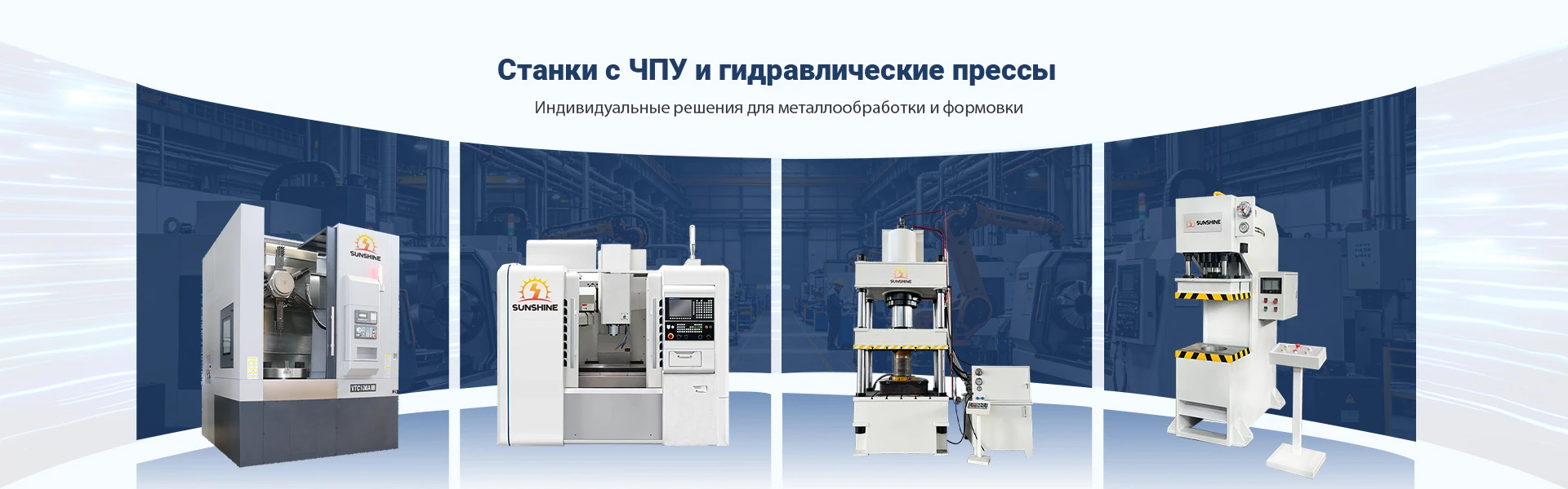
Hydraulic presses are classified as either vertical or horizontal based on the direction of the applied force. Most hydraulic presses are vertical, whereas those used for extrusion are predominantly horizontal. Structurally, they come in various configurations, including two-column, four-column, eight-column, welded-frame, and multi-layer steel-strip-wound frame designs; small-to-medium vertical presses may also utilize a C-frame design. C-frame presses offer open access on three sides for convenient operation but possess lower rigidity. Welded-frame presses used for stamping offer high rigidity and are open at the front and back but enclosed on the sides. In a top-driven vertical four-column free-forging press, the cylinder is fixed within the upper beam, and the plunger is rigidly connected to the moving crosshead; the crosshead is guided by the columns and moves vertically under the pressure of the working fluid. A movable worktable is mounted on the crossbeam. An upper anvil and a lower anvil are installed beneath the movable crossbeam and on the worktable surface, respectively. The working force is borne by a frame assembly consisting of the upper and lower crossbeams and the vertical columns. Large and medium-sized free-forging hydraulic presses driven by pump-accumulator systems often employ three working cylinders to provide three levels of working force. In addition to the working cylinders, balancing cylinders (which exert upward force) and return cylinders are also provided.


